A educational lesson note on Light Geometry and Object – Camera Lighting from Advanced Illumination.
Texture, surface color, shape and composition can all influence how much of the incident light is reflected onto a vision camera and greatly altering the inspections results. For example, it’s difficult to uniformly and consistently illuminate the surface of a highly specular cylinder for print OCR.
Coaxial Lighting Geometery Testing
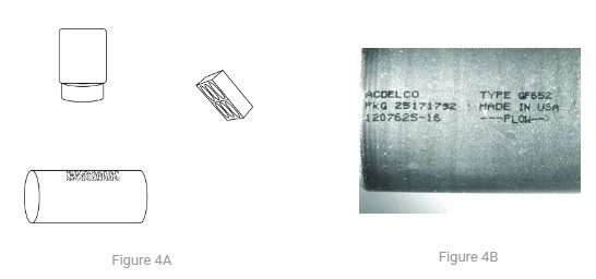
 A metal automotive inline fuel filter is being inspected in this example. A dot matrix type print using black ink is parallel to the cylinder’s long axis. Most print reading applications are set up using a standard coaxial lighting geometry. The camera is positioned perpendicular to the print, and the lighting is a typical coaxially mounted directional ring light. This 3D camera–object–light geometry works well if the object is composed of a diffuse, non-reflective material, and is relatively flat. However, in this instance, the surface is not only specular but also curved in one direction. As shown, using the typical coaxial geometry produces an unsatisfactory, non-uniform image.
In Fig. 1A set-up, the 3D envelope that includes the spatial relationships among camera–object–light is actually a 2D geometry, because the light is coaxial with respect to the camera. As the camera–object orientation must remain the same to maintain image perspective, it would be appropriate to explore changing the orientation of the light, relative to the object and camera. Adjusting Camera – Object
Light Geometry
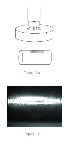
Moving along the cylinder’s direction of curvature and the ring light off-axis away from the camera generates a slightly improved images as depicted in Fig. 2A. As a result it still similarly unsatisfactory image to that of Fig. 2B. The image may be readable in its present form, however this geometry does not allow for any difference in feature placement or object, particularly rotational. This is not a strong image.
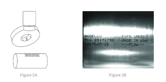
In the case of Figs 2A and 2B, light geometry, they have not significantly changed the object–light geometry with respect to the cylinder axes though the camera was change. Thus, by moving the light both off-axis from the camera and off-axis to the object, while remaining coplanar with the cylinder long axis, They can generate an uniform, consistent, and robust image (Figs. 3A & 3B).
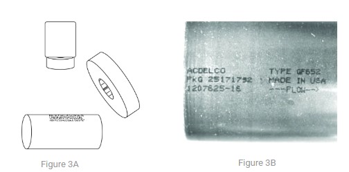
A consequence of moving the light off-axis is a loss of maneuvering room near the object. This can be overcome by using a high-brightness, high-current spot light at a longer working distance in a similar geometry (Figs. 4A & 4B).